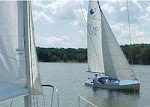
Thursday, June 15, 2006

DECK AND HULL


" A HAPPY LINK OWNER"


HULL TO DECK JOINT
The original deck was pop rivetted to the hull.
The rivets were working loose in the fibreglass deck and hull.
All the rivets were replaced with nuts and bolts, with large washers after silicone was applied to the joint.

The rub strip covers the junction of the hull and the deck.

P.S. Several people have asked about the name of Donal's boat - "PIRAGUA"

Outlined below is the reply I received from Donal on Aug.27/06

"The word piragua is Spanish for dugout, a canoe made from a hollowed out tree.

It would have been commonly used by the Spanish to describe the typical native Amerindian boats they saw in South America and the Caribbean.

In Trinidad, where I was born and raised, a typical planked wooden fishing boat was called a pirogue, the French word for piragua.

I chose piragua for my Link sail boat because of the more direct connection to the original dwellers --and boaters -- of the Caribbean, the Caribs. My research indicates the Spanish co-opted the word piragua from the Caribs."

Donal O'Connor

BUMPER STRIP
Where the bumper strips met at the bow, there was a very sharp bend in the trim which resulted in a very poor fit of the rubber insert. An aluminum bow fitting was made up to cover the ends of the rubber trim.

BOW EYE
A bow eye is designed for pulling the boat as it is well supported by a backing plate. The bow eye was showing signs of stress [nuts sinking into the fibreglass] from hitting obstructions [docks, etc.] A stainles plate, curved to fit the bow profile was attached to spread any impact on the bow eye over a larger area.
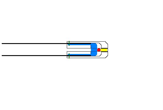


MOTOR MOUNT WELL
The motor mount well had a rubber tube sticking up 1/2" into the well, to drain the well but it did not drain completely. If the rubber tube slipped out of the well, the water drained into the hull.
An aluminum block was made up that attached to the transom and the well with bolts that threaded into the block.
The well now drains completely and the block can never slip out of position.
The rubber insert came around the corners and across the stern- the rubber insert kept coming out of the trim holder at the corners.
The rubber strip across the transom was replaced with a stainless steel strip which also allowed the installation of an outboard motor.


RUDDER GUDGEONS
The original gudgeons were 1/8" stainless steel straps bent at a 90degree angle.
The holes for the pintles were badly worn and the pintles were showing wear from the thin stainless straps.
The straps were replaced with right angled aluminum gudgeons that had much more bearing area for the pintles to rotate in.

LAZARETTE COVER
The hinges on the lazarette cover were removed and replaced with studs that allowed the cover to be removed when the rudder assembly was installed.


INSPECTION PORTS
In order to tighten the nuts and bolts that were installed in the hull to deck joint, inspection ports were installed in the area above and below the seat area.
This also allowed the floatation foam to dry out in the off season.

Friday, June 09, 2006

MAST, SPREADERS AND BOOM


SPREADER INNER END


Because the LINK mast is so limber, proper pivots were made up for the inner ends of spreaders that allowed the spreader to swing fore and aft as well as up and down.


SPREADER OUTER END


Spreader outer end kept slipping on shroud.

Secure fittings were made for outer end that ensure slippage would not occur.


Blue-aluminum plug fits inside spreader[pushfit inside spreader] head is same O.D. as spreader[radius corners well so that shroud does not go over sharp corners]-Core drilled out to allow 1/8" wall inside spreader[to allow rivet head to expand]
Yellow-1/8"stainless pipe plug-27T.P.I.
Red-1/8" shroud wire
Green-3/16" aluminum pop rivets. They can easily be drilled out to remove shroud, if necessary.
Cap is made from aluminum-1/4" larger than spreader O.D. to allow 1/8" wall around spreader 1/8" slot cut top and bottom to allow shroud to be installed.
Use caution when tapping plug hole so that plug traps wire securely before plug threads [tapered] bottom against cap threads].
Cap body bored out to spreader O.D. to depth of slot.[Radius end of cap well so that fore-sails and main sail do not rub against sharp corners].


BOOM CRUTCH


Suports were made up for a boom crutch that would prevent end of boom marking top of lazarette cover.


GOOSE NECK SLIDE

After the main sail is pulled as high and as tight as possible and cleated, the gooseneck can be left at the top of slide for light winds [creating a powerful sail] or for stronger winds, the boom can be pulled to the bottom of the slide [creating a flatter sail shape]

MAIN SHEET SYSTEM


MAIN SHEET ANCHOR
Original main sheet anchor was screwed to floor of cockpit.
[Notice the dark spot between the two hiking straps]


An aluminum pad was mounted and thru bolted thru trunk.

CENTERBOARD AND THWART


CENTERBOARD
The original centerboard was made from plywood and coated with fibreglass.
The wood had started to delaminate and rot had set in.
Made a new centerboard from 5/8" thick 6061 aluminum.
The new centerboard has stood up well.


THWART
The wooden support under the thwart had started to rot and the thwart was starting to crack because of the lack of support.
Made a stainless steel support out of 1/16" stainless steel.

SELF BAILERS
The self bailers were removed as they were a continual source of leaks and they did a poor job of draining the cockpit.
Donal has applied a coat of epoxy paint to the cockpit floor and the original holes are barely visible.


CENTERBOARD PULL-UP
The centerboard pull-up was moved to rear of centerbord trunk to allow the helmsperson to pull up centerboard when going from a close reach to a plane.

JIB/GENOA SHEET FAIRLEADS


ORIGINAL JIB SHEET FAIRLEAD LOCATION
Stainless plate shows where original jib/genoa fairlead was located.
That location did not allow the jib or the genoa to set properly.

JIB SHEET TRACK FAIRLEAD
The jib sheet works well where the fairlead track is currently located but would function even better if installed on seat [holes are still visible but Paul Carter elected to move fairlead track as he thought it was to uncomfortable for his crew to sit on].


GENOA SHEET TRACK FAIRLEAD LOCATION
Genoa fairlead proper location.
Installed turning blocks for genoa sheets before determining proper location for fairlead track.

RUDDER ASSEMBLY

A. If a rudder pull-up system is not effective and secure, the rudder could be damaged [hitting the ground] when boat is launched or retrieved.

B. If the rudder does not have a hold-down arrangement that works well in heavy weather and the rudder is allowed to trail straight out behind the craft, a VERY heavy tiller results, as well as the more serious problem of possibly breaking the tiller or the rudder because of the EXTREME leverage exerted by the rudder being straight out behind the pivot point.


C. Improve method of rudder hold-down and pull-up - rope and cleat concept has problems- if rudder has run aground, rope tension increases dramatically and sometimes the only way to free rudder is to cut hold-down rope.
Rudder pullup and transport clips [shown in full down position] which results in a balanced rudder.
Clip is used for launching and retrieving boat, with the rudder installed.
Rudder hold down and pull up spring + 1/8" wire strop [pivots from rudder head bolt to stand/off on rudder]. Spring is 9" closed length and expands to 13" when moved thru full arc [full down to full up].
The spring concept has performed beautifully.
Even in heavy winds, the rudder remains very light to the touch and we can be confident that if the rudder ever needs to go up, if it encounters an object, it can.
Also, if one encounters thin water where one runs the risk of hanging up the rudder [if the centerboard has been pulled up completely] the rudder pull-up works well.