.jpg)
Blake's ALBACORE was manufactured by KOMA boats, using many items found on LINK sailboats.

 must guard against one sail blanketing another. Blanketing occurs when the forward sail comes into the wind shadow of the after sail and is starved of non-turbulent air. This situation is caused by sailing by the lee, and the obvious solution is to head up a bit to give the forward sail clean air or, when a spinnaker is not carried , jibe over one of the sails and sail wing-and-wing.


" A HAPPY LINK OWNER" .24.jpg)
HULL TO DECK JOINT
The original deck was pop rivetted to the hull.
The rivets were working loose in the fibreglass deck and hull.
All the rivets were replaced with nuts and bolts, with large washers after silicone was applied to the joint.
The rub strip covers the junction of the hull and the deck.
P.S. Several people have asked about the name of Donal's boat - "PIRAGUA"
Outlined below is the reply I received from Donal on Aug.27/06
"The word piragua is Spanish for dugout, a canoe made from a hollowed out tree.
It would have been commonly used by the Spanish to describe the typical native Amerindian boats they saw in South America and the Caribbean.
In Trinidad, where I was born and raised, a typical planked wooden fishing boat was called a pirogue, the French word for piragua.
I chose piragua for my Link sail boat because of the more direct connection to the original dwellers --and boaters -- of the Caribbean, the Caribs. My research indicates the Spanish co-opted the word piragua from the Caribs."
Donal O'Connor
BUMPER STRIP
Where the bumper strips met at the bow, there was a very sharp bend in the trim.0.jpg) which resulted in a very poor fit of the rubber insert. An aluminum bow fitting was made up to cover the ends of the rubber trim.
which resulted in a very poor fit of the rubber insert. An aluminum bow fitting was made up to cover the ends of the rubber trim.
BOW EYE
A bow eye is designed for pulling the boat as it is well supported by a backing plate. The bow eye was showing signs of stress [nuts sinking into the fibreglass] from hitting obstructions [docks, etc.] A stainles plate, curved to fit the bow profile was attached to spread any impact on the bow eye over a larger area.
MOTOR MOUNT WELL
The motor mount well had a rubber tube sticking up 1/2" into the well, to drain the well but it did not drain completely. If the rubber tube slipped out of the well, the water dr.0.jpg) ained into the hull.
ained into the hull.
An aluminum block was made up that attached to the transom and the well with bolts that threaded into the block.
The well now drains completely and the block can never slip out of position.
The rubber insert came around the corners and across the stern- the rubber insert kept coming out of the trim holder at the corners.
The rubber strip across the transom was replaced with a stainless steel strip which also allowed the installation of an outboard motor.
RUDDER GUDGEONS
The original gudgeons were 1/8" stainless steel straps bent at a 90degree angle. .0.jpg)
The holes for the pintles were badly worn and the pintles were showing wear from the thin stainless straps.
The straps were replaced with right angled aluminum gudgeons that had much more bearing area for the pintles to rotate in.
LAZARETTE COVER
The hinges on the lazarette cover were removed and replaced with studs that allowed the cover to be removed when the rudder assembly was installed..2.jpg)
INSPECTION PORTS
In order to tighten the nuts and bolts that were installed in the hull to deck joint, inspection ports were installed in the area above and below the seat area.
This also allowed the floatation foam to dry out in the off season.
 SPREADER INNER END
Because the LINK mast is so limber, proper pivots were made up for the inner ends of spreaders that allowed the spreader to swing fore and aft as well as up and down.
.9.jpg)
SPREADER OUTER END
Spreader outer end kept slipping on shroud.
Secure fittings were made for outer end that ensure slippage would not occur.
Blue-aluminum plug fits inside spreader[pushfit inside spreader] head is s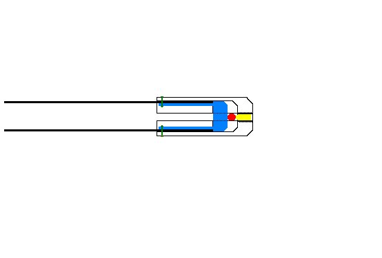 ame O.D. as spreader[radius corners well so that shroud does not go over sharp corners]-Core drilled out to allow 1/8" wall inside spreader[to allow rivet head to expand]
Yellow-1/8"stainless pipe plug-27T.P.I.
Red-1/8" shroud wire
Green-3/16" aluminum pop rivets. They can easily be drilled out to remove shroud, if necessary.
Cap is made from aluminum-1/4" larger than spreader O.D. to allow 1/8" wall around spreader 1/8" slot cut top and bottom to allow shroud to be installed.
Use caution when tapping plug hole so that plug traps wire securely before plug threads [tapered] bottom against cap threads].
Cap body bored out to spreader O.D. to depth of slot.[Radius end of cap well so that fore-sails and main sail do not rub against sharp corners].
BOOM CRUTCH
.23.jpg)
Suports were made up for a boom crutch that would prevent end of boom marking top of lazarette cover.
GOOSE NECK SLIDE
.jpg)
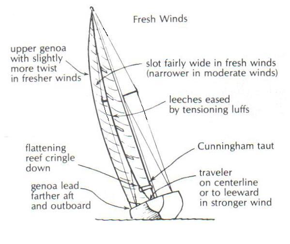
After the main sail is pulled as high and as tight as possible and cleated, the gooseneck can be left at the top of slide for light winds [creating a powerful sail] or for stronger winds, the boom can be pulled to the bottom of the slide [creating a flatter sail shape]
.jpg)
.jpg)
.jpg)
.jpg) ting to crack because of the lack of support.
ting to crack because of the lack of support. .jpg)
.jpg)
.0.jpg)
.jpg) A. If a rudder pull-up system is not effective and secure, the rudder could be damaged [hitting the ground] when boat is launched or retrieved.
A. If a rudder pull-up system is not effective and secure, the rudder could be damaged [hitting the ground] when boat is launched or retrieved..jpg)